Die-sink EDM forms complex parts
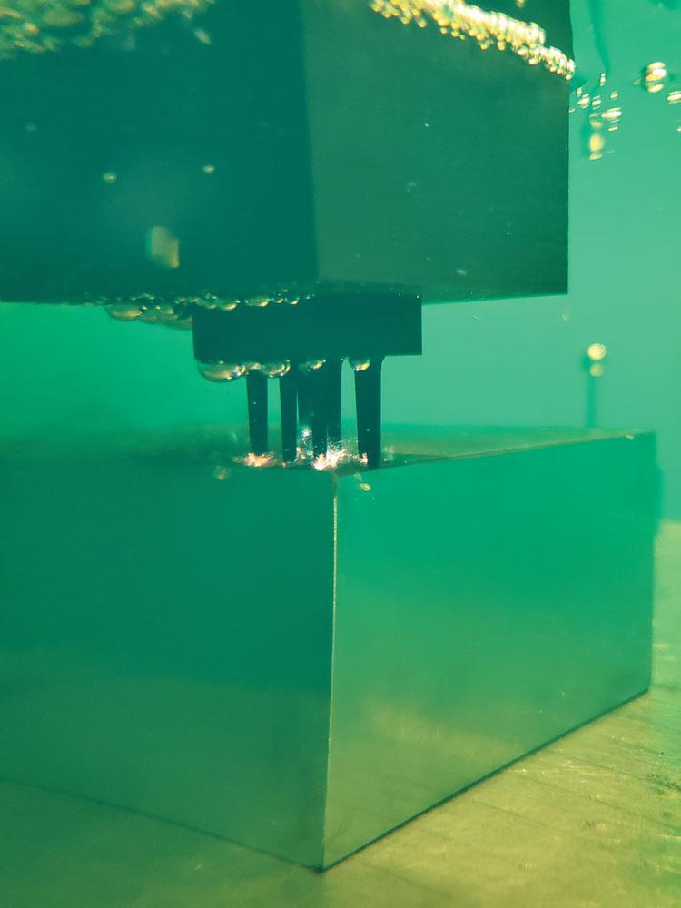
The sinker EDM’s carbide probe locates the work area. The probe also can check tolerances of features that are burned before removing the finished part. Photo courtesy of MC Machinery.
Electrical discharge machining (EDM) is a unique process. The shapes and tolerances produced by this method are next to impossible to create using traditional machining techniques.
These abilities, combined with a high demand for complex parts from the automotive, aerospace, and medical sectors, are making EDM a must-have for modern shops. Die-sinker EDMs, in particular, often can solve the problems posed by machining materials such as high-nickel-content alloys used in the aerospace industry. Also, the complicated shapes and deep pockets commonly found in the mouldmaking industry are two part features that pose a challenge to CNC chipping machines. However, these geometries lend themselves well to the CNC die-sinking process.
These machines can produce both through-cavities and blind cavities using a graphite or brass electrode.
How It Works
Die-sinker EDMs work by using an electrical discharge to erode workpiece material.
When electrical voltage is applied and becomes high enough, a breakdown of the dielectric occurs. The electrical current circulates through the ionized channel and the discharge is created. Thousands of these discharges are created per second, with the number and intensity affecting cut speed and surface finish. Control and generator technology make it possible to control the duration and the intensity of the discharge.
It’s actually a six-part process:
When the control senses irregularities in the discharge or gap voltage, it changes the system’s on-time, off-time, jump cycle, and servo gain to adjust the conditions in the cutting gap to minimize wear of the electrode.
The dielectric fluid’s role is to help control the spark by maintaining a precise conductivity. The fluid also flushes away burnt metal from the erosion zone.
Electrode Importance
The EDM’s electrode is as important to the success of the operation as the hardware and software. No erosion can take place without some sort of an electrode.
The electrode also serves as the model that produces the desired forms. A negative of the electrode’s shape is created in the workpiece during the erosion process. For every negative feature on the electrode, a positive feature is produced in the workpiece and vice versa.
The sinker EDM’s adaptive control enables the machine to adjust parameters as surface area flushing and discharge gap conditions change. Photo courtesy of MC Machinery.
In most cases, it also takes several electrodes with varying shapes to develop the part’s final form. However, advances in orbiting can reduce the number of electrodes needed for the process.
Improving Productivity
Having a productive die-sink EDM process is relatively straightforward: Create the correct work environment, use up-to-date technology, and eliminate rework.
Improving productivity in die-sinker work might not be top of mind because of the complex nature of the work and because it's a little bit slower process, but it still can make a difference. And it all starts at the beginning.
“Having your machine set up and ready with the right electrode and the right material all at the same time may sound simple, but it’s an important first step. Having to wait because one piece of the puzzle isn’t ready is a major waste of time,” said Eric Ostini, head of business development, senior product manager – EDM, GF Machining Solutions, Lincolnshire, Ill.
It’s also different for a shop that has one die sinker as opposed to an automotive supplier that may have a whole line of them. As the number of machines, electrodes, and electrodes per machine increases, so does the chance of an error.
Modern software and the elimination of manual inputs helps ensure that errors are reduced.
“It’s easy to feel overwhelmed when you have 20 or 30 electrodes sitting on the workbench and you have to figure out where they all go,” said Ostini. “Following the CAD/CAM model really does help with this.”
A new addition to GFMS’s software, the True Response to User Expectation (T.R.U.E) system, also aims to improve productivity by optimizing the entire process from electrode creation to cavity creation and even measurement.
According to Ostini, the CAD/CAM system analyzes the part’s form and designs an electrode for which the ideal undersize (how much smaller the electrode is than the cavity it is creating) has already been automatically calculated.
During the job preparation sequence, the data gathered in CAD/CAM preparation is transferred for work order data generation, including manufacturing order and part identification. In the execution sequence, either for a stand-alone machine or for an entire production cell, the software ensures that the EDM process always uses real data based on the true geometry of the electrode and part.
The dielectric fluid’s role is to help control the spark by maintaining a precise conductivity. The fluid also flushes away burnt metal from the erosion zone. Photo courtesy of GF Machining Solutions.
“What is being demanded more and more worldwide is to reduce the number of electrodes you need in order to produce the cavity,” said Ostini. “This means you need a generator that can adapt between speed and finish. You can program the generator for more accuracy than speed or finish. And today the need has been more towards low wear because if you do this, you can either use the same electrode over and over and over for cavities or use fewer electrodes per cavity.”
Using a CAD model reduces human error because there are fewer manual inputs as well.
“It’s less likely that somebody types something in wrong like depth or the undersize if all the data involved in the process is already part of a CAD file,” said Pat Crownhart, national sinker EDM product manager, MC Machinery Systems, Elk Grove Village, Ill. “It speeds up the process and avoids errors.”
Once a part is set up on the machine, it’s time to start producing the cavities.
Generator Technology
The EDM’s generator technology creates sparks while controlling electrode wear and optimizing cutting speeds. On certain die-sinking EDM equipment, the technology manages the electrical current between the fronts and sides of electrodes and controls its delivery to minimize lateral sparking that disrupts effective machining of areas such as the sides of mould cavities. The system allows the electrode to have maximum power in the front of the cavity without destroying or creating oversize gaps on the cavity side walls.
“Spark size and shape is very important to the process,” said Crownhart. “There is a direct relationship between spark size, shape, and number of sparks and cut speed and quality. If you are generating a big spark, you may be generating 8,000 sparks per second, but if you’re talking about a small spark, you’re up to 40,000 sparks a second or more. Big sparks will remove larger amounts of material than small sparks, so it’s important to be in control of these functions.”
The number of sparks and their shape are controlled by the EDM’s amperage and on-time. These are adjusted to control speed and are also based on material type.
The right spark has to be tailored to the material being eroded, said Crownhart.
“Think of a spark like a tiny shovel removing material. The size and shape of your shovel is determined by what you are shovelling,” said Crownhart. “It’s the same in this process. The size and shape of the spark also determines how much material you are removing, so it also determines the roughing and finishing of a part.”
Gap Distance
The material and size and depth of a cavity also affect the gap distance, which is the distance between the electrode and the part. Typically, this distance is around eight or nine thousandths of an inch. This gap distance during final fine finishing, however, can be as little as a 10 thousandths.
Multiple electrodes are used to create parts on a die-sink EDM. Photo courtesy of GF Machining Solutions.
Before the cavity is finished, an orbiting cycle is performed. This cycle uses small, weak sparks in combination with movement of the electrode to make the final part form. Electrodes are manufactured slightly smaller than the form to take this step into account.
On-machine Measurement
Today an EDM can use a touch probe system or use its electrode as a probing system to check for part location and dimensional accuracy. A part can be probed before it is machined to determine its exact orientation in the work tank and during the machining process to verify that the cavity has been burned to the proper size.
“A touch probing system is not as accurate as using the electrode to touch the part, but the benefit of touch probe is that, because electricity isn’t being used, it won’t mark the part,” said Ostini. “So, if I'm touching off on a shiny surface with an electrical touch, I will mark it with the spark that comes from the electrode.”
Using eithera touch probe system or an “electrical touch,” you get some of the benefits of measuring on a CMM without removing the part from the machine.
“The measuring process can be automatic, meaning that it measures immediately after it's done producing the cavity. If it finds that it is still not the right size, it tells the machine to go back into the cavity with the electrode and do some more work,” said Ostini.
Editor Joe Thompson can be reached at jthompson@canadianmetalworking.com.
GF Machining Solutions, www.gfms.com
MC Machinery Systems, www.mcmachinery.com
As surface area ramps up and gap conditions improve, a quality EDM should increase discharge frequency, resulting in better machining speeds and increased productivity. Photo courtesy of MC Machinery.


